Thunderbird
an original overdrive inspired by the classic sound of a cranked 100W Marshall Super Lead amp
| This project is rated 3 out of 3 for the level of complexity. |
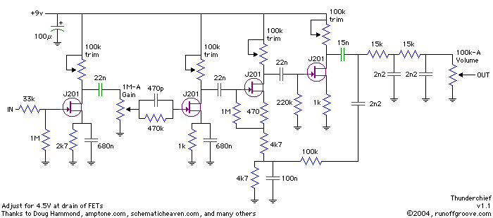
The circuits developed by runoffgroove.com have historically been focused on the balance between good tone and circuit complexity. Our previous attempts at capturing the sound of the cranked Marshall Super Lead amplifier sound used this approach, resulting in the Thunderchief (2004) and Thor (2006) pedals.
This time we wanted to take the circuit to a new level by relaxing the simplicity constraints in favor of flexibility and tone. Additionally, we set the goal to use quality and accessible parts that would ensure the sound of each build is more or less the same. Use of JFETs is incompatible with this requirement, as is the tone relying how a particular op-amp or CMOS gate reacts to input overdrive and supply rail clipping.
That brought us to the following design parameters as the starting point:
Some fans of our past JFET circuits may be ready to dismiss this project, thinking we have gone out of our minds, but we will implement the required nonlinearities and signal asymmetries in a different manner.
With the above criteria established, we set to the task of modeling a boutique-modified 100W Marshall Super Lead that possessed the magic tone we hoped to capture in pedal form. That particular amplifier, owned by a member of the runoffgroove.com team, provided the baseline and allowed side-by-side comparison during development.
Looking at the target amp we found two input channels, NORMAL and BRIGHT. The BRIGHT channel has the option to include a treble-bleed cap in the GAIN control for extra brightness. Looking at all this we wondered: wouldn't it be nice to have these three tonal options in our pedal? Certainly!
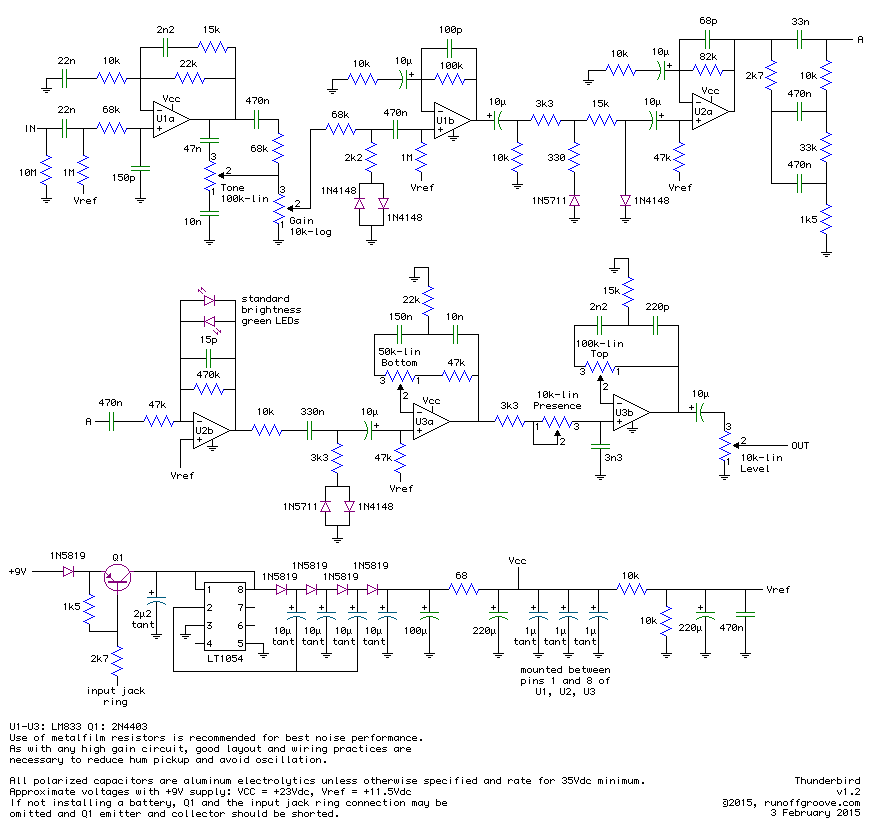
A three-position switch could achieve the task, but the original amp wiring that allows mixing the NORMAL channel into the BRIGHT channel for extra body, so in the end we found a way to implement a TONE control that varies continuously between the three aforementioned options, as you can see in the final design. In addition, the frequency response of this TONE control is not altered as the GAIN pot position is changed, which in a typical amp would render the BRIGHT capacitor useless as the GAIN is dimed.

Next, a key challenge followed: how to implement the asymmetric clipping coming from the preamp overdrive. Different numbers of diodes for each signal polarity have been used ad-nauseam for this purpose, and yes, this does add some second-order harmonics. We were looking for something more accurate and wanted to include the following aspects in our circuit:
We studied many patents related to triode emulation, duty-cycle variation based on signal level, and also some digital implementations that do model these dynamic effects. Combining the knowledge gained by the above, we came with our own analog circuit which accomplishes this in a very simple but effective manner, as you can see between the second and third op-amps. This circuit may appear deceivingly simple, yet it has all the characteristics described above, with the only requirement being that it has to be driven by a stage with a high dynamic range, hence the 24 Vdc supply requirement. The key about the dynamic level shift is briefly described in the next paragraph:
The 10 uF capacitor following the second op-amp starts to develop a DC voltage as signal passes through because the positive and negative cycles have unequal resistors to GND through each diode. The imbalance between the resistors to each diode (3k3+330R for negative signals, 3k3+15k for positive signals) determines the prominence of the effect. As the DC voltage develops across this capacitor, both clipping thresholds are affected accordingly. Finally, the 10k resistor to GND just after the 10u capacitor is there to discharge the capacitor when no signal is present.
A fixed tonestack follows, and next a rather hard clipping stage based on green LEDs. This stage accounts for the phase inverter clipping - the predominant source of distortion as verified with the original amplifier. After this, a soft clipping stage represents the output transformer and power amp clipping. At this point we knew that neither the phase inverter nor the power amp are perfectly symmetrical, and we found that using different diodes (with different conduction thresholds) in this last stage actually added to the quality of the circuit. Another benefit of this soft-clipping diode arrangement at the end is that it provides a softer transition from high to low level signals, which is audible as the amount of clipping and grit gradually fades out instead of having an all-or-nothing characteristic of many hard-clipping pedals.

A powerful set of toneshaping controls follow. The BOTTOM control can add almost 15 dB of bass boost centered around 100 Hz. The TOP control can add up a bit more than 15 dB of treble boost centered around 6000 Hz to provide as much bite as necessary, and beyond. Boosting both controls will yield a scooped mids response which is great for rock sounds. Use these controls above 15:00 at your own risk! (In some setups extreme settings may produce clipping or feedback, so use your good judgement.)

Lastly, a PRESENCE control was implemented to provide additional top-end control and properly match the pedal to different types of amplifiers and speakers.

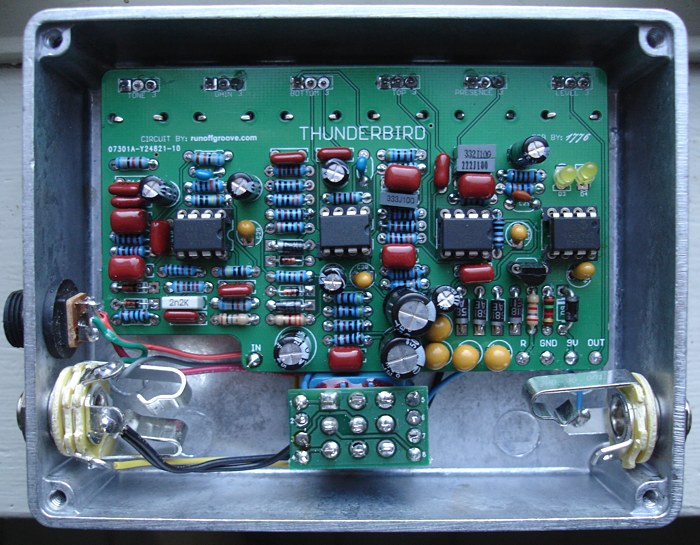
Josh McClarren of 1776 Effects contributed a Thunderbird PCB layout (PDF, 481k) and sells ready-to-solder Thunderbird PCBs.

Thunderbird by runoffgroove.com is licensed under a Creative Commons Attribution-NonCommercial-ShareAlike 3.0 Unported License.
Permissions beyond the scope of this license may be requested.